I have not made a post in forever, and for almost good reason. You see, aliens hijacked my blog so I couldn't sign in. They also started another semester of school and the beginning of a robotics competition. Oh, they started maximizing the Humble Indie Bundles and stuff as well. It's not as if you care anyway. You're probably just future me as usual, so time doesn't pass at the same rate and you don't need to worry about waiting three months to read the next post. It's like a good webcomic you just figured out about. You read hundreds each day, and when you get to the last one, you realize crap, now I need to wait for a week for the next one.
On a slightly related note, The sudden stop in quadcopter production posts was because I found it hard to upload so many pictures and talk about each one. I think some day I'll need to make a more organized version of that. The whole "I'm a beginner and that should make it easier to understand" is not the way to go about tutorials. Don't do that. Speaking of the quadcopter, someone flew it, but it wasn't me. When I tried to fly it, I could only get a few inches off the ground without crashing out of sheer fright. Eventually one of the motors broke and I had to wait a month to get new ones. I upgraded the frame, and now it won't work because I shorted out the Arduino in the process; I need a new one. Aaaaaanyway, I'll update when that's done. In the future, I'll make a much more organized version and document that.
I've decided to make another blog. Not another account, but a blog on this account. This account is primarily composed of stuff I wrote the year I was homeschooled. I've decided to keep it that way for scientific purposes. No need to say thank you, future me. I'll leave the past 20 or however many posts I've made since that year, but I'll be updating the other one from now on. I'm going to make it my goal to update once a week... starting next week. Just kidding. I really don't know how effective that will be. Hopefully an update a week won't kill me.
I'm not sure exactly how this next blog is going to go. It will probably involve everything from playing games to listening to music to hobbies I pick up as life goes on. Maybe tutorials as well, but not things like that quadcopter failure (remember, the quadcopter wasn't a failure, the quadcopter "tutorial" was). If I try something new, I'll purely document it. There will be no "how to" involved. Sooooooooooooooooooooooooooooooooooo...
Tuesday, February 28, 2012
Thursday, October 20, 2011
Quadcopter-Change of Plans
Yesterday, I went to Charlotte Hackerspace, which was doing a workshop-type thing on building quadcopters. I talked to the guy in charge of it, and he told me a bunch of helpful things, and I saw things that have influenced the way I'll build the quad. The first thing that changed was the code I'm using. I'll now use the beta code and configurator instead of the 2.7.1 code and configurator. Also, I found out what the configurator does. It programs the escs and calibrates the transmitter. Simply put, it does the hard stuff that I was worried about. I found out how I'm going to build my frame and mount my motors. I'm going to build a wooden frame, and attach the motors in a way I'll describe some other time. He also told me to use a different type of wire. The kind you can't find at radio shack. This is the kind of wire used on the battery, escs, and motors. It's silicon-covered, and has a more rubbery feel than normal wire. It's also more flexible and better for soldering because it doesn't shrink or anything. He gave me a cool piece of metal with copper on both sides separated by silicon. That way, I can send the positive current through the top and the negative through the bottom for simplicity instead of splitting a wire in a complex way. He told me I only needed three of these, which I was amazed by. I thought I needed six, and I would have if I didn't know what certain slots in the receiver were for. I'll go over that in the documentation. I'm also going to get shrink wrap to make connecting the motors and escs better. I was pretty stupid not to think of that before. I don't have a heat gun, but I think you can use a lighter. That's all. I hope to have the quad done in less than two weeks. Honestly, it's a weekend's worth of work if you know what you're doing, but I procrastinate, and now it's been about six months. That's all I have to say right now. Expect another documentation on Monday or something.
Sunday, October 16, 2011
Quadcopter Documentation/Tutorial 4: Charging the Battery
I've realized that since there are so many tutorials out there, I'm doing a documentation of my experience rather than trying to help others, which this can still be used for, by the way. That's why I'm calling it a documentation/tutorial because the primary purpose is to record my experience while a secondary purpose is to help beginners such as me.
Today I soldered some bullet connectors (which I need to get more of and charged my battery for the first time. I'll explain everything in the order I did them:
The first thing I did was cut the lengths of wire I needed. I used a wire cutter/stripper, but I think there are other options (although I'm not sure trying to cut with scissors would be a good idea. Since I was only going to use these lengths for charging, I cut them relatively short.
 I cut two of these. If I were professional, I would have cut one red wire and one black wire for positive and negative, but I only have this roll of 16 gauge wire and I don't feel like going out and buying more. I then stripped each end with the same tool. If you don't have a wire stripper, use a knife. You can cut the end off, but it's usually not as neat.

 At first, I stripped too much off. There was still wire showing after placing the ends in the bullet connectors. The ends should end up looking more like this (about half as long:
 After cutting and stripping the wires, I went outside and got my solder and soldering iron ready. I used the 30 watt setting of my soldering iron and I used .062" diameter solder.
 The first thing I did was cover one of the ends of one of the wires in solder. That way, It fills up empty space in the bullet connector.
 I then put the bullet connector pointing up on an alligator clamp. It's important to have something like this because it gets hot and is hard to hold in this position otherwise. I filled it mostly with solder, then I put the soldered end of the wire into it. If it dries before you can put the wire in, heat it up with the soldering iron as you place it in. Solder melts easily, but dries fast.

 I did this with both bullet connectors: one on each wire. I couldn't get the red protector on right, but know how now, but too late. I'll demonstrate when my new ones come in. Instead, I put electrical tape around the sections that would be exposed. It works, but isn't as elegant.
 Plugged into the battery, they look like this:

 I started by using the alligator clips. I clipped them to the exposed ends of each one of the soldered wires. Make sure the red alligator clip is on the male bullet connector and the black one is on the female one. Also make sure they're plugged into the right slots in the charger.
 Afterwards, I plugged the bullet connectors into the battery and plugged the battery's balance plug into the charger.
 I actually did the next step first because I wasn't thinking properly. All it is is plugging the charger into the wall. It doesn't make much difference when you plug it in, but it's a tiny bit safer if you wait.
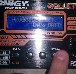
 I then had to go through the charger's menu to charge my battery properly. First, I had to choose LiPo battery, so I just pressed "Type" and cycled through with the left and right arrows until I found it. Then I pressed "Start".
 I then had to get all the values I needed from my battery, which were cells, voltage, and amps. The cells and voltage were already right because of the balancing plug. It automatically assumes 3.7 volts per cell, which I guess is standard. This is a picture of the battery, showing how I found everything:
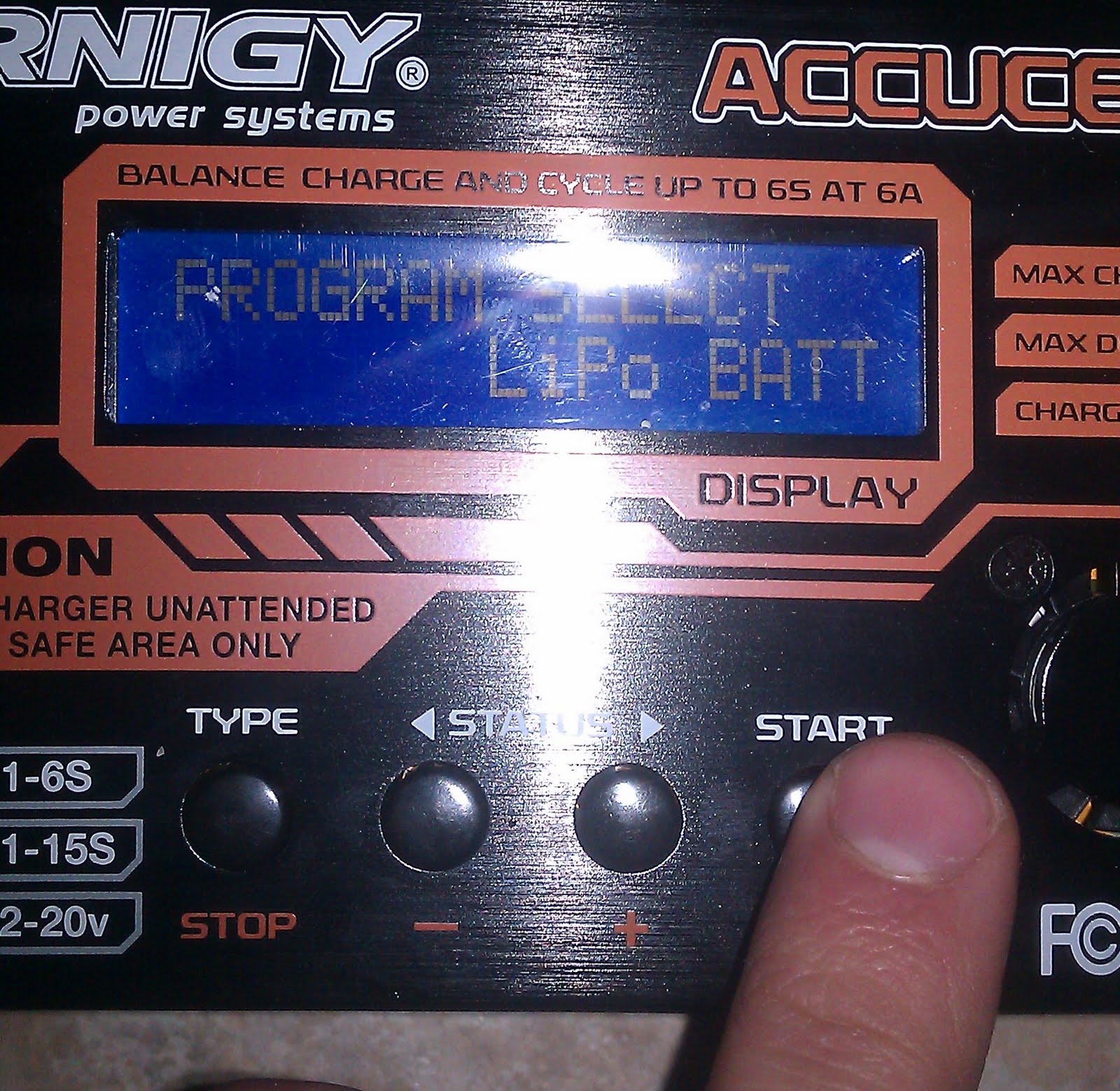
 This is the screen on the charger. 0.4 should be 4.0. I didn't know at the time.
 Here's the whole arrangement before I began charging (minus the alligator clips which got cut off). The yellow boxes show where the connections should be. I held down start for three seconds, then pressed it again to confirm to show the charging screen which you see last.


That's all. My next step will probably be messing around with the transmitter and speed controllers, but I'm not sure how to go about any of it yet.
Today I soldered some bullet connectors (which I need to get more of and charged my battery for the first time. I'll explain everything in the order I did them:
Soldering the Bullet Connectors:
This took a pretty long time because I couldn't get the red protector on the bullet connectors. I ended up using electrical tape instead. I'm ordering more bullet connectors so I can use the red covering since I completely destroyed mine.The first thing I did was cut the lengths of wire I needed. I used a wire cutter/stripper, but I think there are other options (although I'm not sure trying to cut with scissors would be a good idea. Since I was only going to use these lengths for charging, I cut them relatively short.


Charging the Battery:
Now to the primary part: charging the battery. To start, I needed to plug in all the cords to connect the battery to the charger. There are two separate spaces for male bullet connectors on the charger; one for positive and one for negative. There are alligator clips that come with the charger that go here. On the right side are several slots with pins. This is to keep track of the separate cells in the battery when balancing. I'm using the one with four pins since it's decided by number of cells + 1 (for ground I think).


That's all. My next step will probably be messing around with the transmitter and speed controllers, but I'm not sure how to go about any of it yet.
Friday, October 14, 2011
Quadcopter Tutorial 3: Messing around with code and the Arduino
EDIT: Someone is helping me out with the quadcopter, and recommended the beta code and configurator (AeroQuad_v2.5_Beta1.zip and AeroQuadConfiguratorFull_v3Beta2.zip in the AeroQuad downloads section). The code is edited the same way as in this documentation, but I'm also changing my style from plus configuration to x configuration.
So I've finally decided to be productive and post another tutorial. This one will be better because it's more of a documentation, not just a tutorial. I'm writing and taking pictures of what I'm doing as I'm doing it and not afterwards. The reason I didn't do that before is because I had already done those before deciding to make a tutorial. Also, the Aeroquad tutorial on their wiki might be easier, so go there if I don't explain it clearly enough or if I'm more boring-er than them.

 By the way, I definitely took that picture, and my desk definitely is that blindingly perfect and white. I just opened the Arduino.exe in the folder I unzipped. AeroQuad recommends that I test the Arduino out with the "blink" code first, so I will. Basically, this just blinks an LED on the Arduino every second.
 It opens another window with code on it. It looks like Java, but somewhat simpler. I went to the tools tab, then to board, and chose "Uno", because I have the Arduino Uno. The program can't find my Arduino because it can't find the com port. This told me to go to Control Panel>System and Security>System, so I did. I opened the device manager, found the Uno, and browsed for the driver, which was in the folder arduino-0022>drivers. I chose the folder and the drivers were installed. Now on the device manager, this is what I see:
 I can finally get back to testing. I chose the now-available com port:

 As you can see, uploading now works and I see the LED blinking on for one second, then blinking off for one. Now to the real code.
 This is extremely simple. Just uncomment whatever you're using (take away the "//"), so I uncommented "#define AeroQuad_v18" since I'm using an Arduino with the AeroQuad 1.9 shield (which is essentially the same as the 1.8).
 The flight configuration is how the propellers are arranged relative to the front of the quad. The basic ones are X and +. X is meant for fpv quads, or quads with cameras on them so the propellers aren't blocking its view, but it seems more complex for me, and I'm not using a camera, so I chose the + configuration:
 There are three optional sensors: the barometer, magnetometer, and battery monitor. I don't have either of the first two, and I'm not using the battery monitor until I'm already finished, so I uncommented only the last choice:
 The next section has to do with flight angle calculations. Basically, you uncomment the ARG line if you don't have a magnetometer and otherwise leave it. I don't have a magnetometer, so I uncommented it:
 The remainder of the user-definition section is about camera stabilization and stuff that I don't care about (currently), so I'm done!
I uploaded the code to the Arduino with no problems. If you need any help, comment.
So I've finally decided to be productive and post another tutorial. This one will be better because it's more of a documentation, not just a tutorial. I'm writing and taking pictures of what I'm doing as I'm doing it and not afterwards. The reason I didn't do that before is because I had already done those before deciding to make a tutorial. Also, the Aeroquad tutorial on their wiki might be easier, so go there if I don't explain it clearly enough or if I'm more boring-er than them.
1. Installing the Arduino Software:
First, I'm going to download the software for the Arduino, which can be found here. I chose my operating system, which is Windows. You need to download a zip file. If you don't have a program that can unzip these, I found a good one here. Be careful when installing it and look carefully at every page. Don't let them trick you with sneaky text into installing some crappy useless Bing toolbar. I unzipped the file into a folder called "quadcopter".2. Downloading the AeroQuad Code:
I went here and downloaded the configurator as well as the code and put them in the same folder as the Arduino software. The links should be the two at the bottom: "AeroQuad_v2.4.2.zip" and "AeroQuadConfigurator_v2.7.1.zip". Simply put, the code tells the quadcopter what to do and the configurator troubleshoots if something doesn't work. My folder now looks like this:
3. Testing the Arduino:
To connect the Arduino, I needed the USB A to B cable, which looks like this:


4. Editing and Uploading the Code:
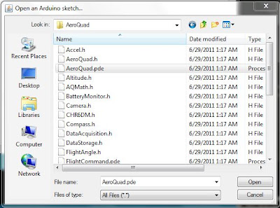
I needed to open the AeroQuad code to start with, so in the Arduino program, I went to File>Open>...>AeroQuad>AeroQuad.pde:


I uploaded the code to the Arduino with no problems. If you need any help, comment.
Saturday, October 1, 2011
[Insert post name here]
So as always when I can't find anything to do, I'm writing here. Actually, I have plenty of things to do. In fact, the total time these things would take could quite possibly be the entire day. I just really don't feel like doing any of them. So, as usual this year, not last, school has been fun, at least compared to usual. I'm half a week to a week ahead in all my classes except Spanish II and Art. I've done all the work I can in Spanish, and I haven't done any of next week's work in Art yet. That's what I need to do, but in order to do that, I need to leave my room, unplug this laptop, take it all the way downstairs, plug it into the printer, print out some stuff, bring the laptop back upstairs, move the things that magically grew while I was gone, and plug my laptop back in. That's probably been the hardest part of my online classes so far. I hate moving my laptop.
I also don't really feel like making another quadcopter tutorial yet because I really don't feel like it right now for some reason. The next tutorial, though will be how to modify the code for the specific quad and how to get that code onto the Arduino.
Finally, the new Humble Bundle is out. This is a collection of indie games for the pc (any OS). It's pay what you want, so you could pay anywhere between a penny and thousands of dollars, and there are people on both ends of that. If you are going to get it, don't pay a penny, because only jerks do that. This Humble Bundle is the Humble Frozen Synapse Bundle. Frozen Synapse is a really awesome strategy game. It's hard to describe how to play, so you'd need to either buy it, or download the demo and try it out, or maybe just watch some videos. Also, if you pay above the average which is about $4.65, you get some indie games from a company called Frozenbyte, all of which look cool. So if you want to get it, go here.
Monday, September 5, 2011
Quadcopter Tutorial 2: AeroQuad 1.9 Shield
So here's the second tutorial. This will be about how to solder the AeroQuad shield together to make the Arduino more user-friendly. I honestly think it might be easier for you to do the tutorial from the AeroQuad wiki here, but I'll be going through things I had trouble with that they might not completely explain.
So to start, this is what the shield will end up looking like in the end. I'll number all the sections so you know what part I'm referring to when.


Before I get started with that, though, I'll talk about soldering. First of all, when you solder, solder outside or somewhere with good ventilation. This is because the solder has lead in it, which you shouldn't inhale. Also, because of this, wash your hands after soldering because you don't want lead going into your mouth when you eat. Solder on a surface that either won't get damaged or you don't mind getting damaged if you accidentally touch it with the soldering iron. The soldering iron gets very hot, so you don't want to touch it either. If your soldering iron is like mine, it comes with a little ring which you can set it on when you're waiting for it to cool down or just want to take a break. This is a picture that shows what that's for, because I didn't know at first:

Since you're doing light soldering, the soldering iron should be 15 watts. If you look in the previous picture, you can see that mine can switch between 15 and 30. Your solder should be .032" in diameter. This is the thinner type meant for things like this.

When you solder, you should have a relaxed grip so that the soldering iron doesn't move around too much. Don't hold your hand in the air, because that's unstable and hard to keep still.

This is extremely easy once you get the hang of it. There are two ways I've found I could do this. One is to heat up the metal you will be soldering onto with the soldering iron and just touch the solder to it to melt onto it. Another way is to touch the solder directly to the soldering iron, which is much faster but a little harder. If you look closely in this demonstration, you can see that surface tension causes the solder to gather in a cone shape at the base of wherever you're soldering, so it's very unlikely that you will accidentally connect two pieces of metal that shouldn't be connected.

If, however, you do accidentally solder something you shouldn't have, simply touch the solder with the soldering iron. It should melt again and stick to the soldering iron because of surface tension. Repeat this until it's all gone.
Now,for the actual tutorial:
Thank you for reading this, and I hope it helped.
So to start, this is what the shield will end up looking like in the end. I'll number all the sections so you know what part I'm referring to when.


Before I get started with that, though, I'll talk about soldering. First of all, when you solder, solder outside or somewhere with good ventilation. This is because the solder has lead in it, which you shouldn't inhale. Also, because of this, wash your hands after soldering because you don't want lead going into your mouth when you eat. Solder on a surface that either won't get damaged or you don't mind getting damaged if you accidentally touch it with the soldering iron. The soldering iron gets very hot, so you don't want to touch it either. If your soldering iron is like mine, it comes with a little ring which you can set it on when you're waiting for it to cool down or just want to take a break. This is a picture that shows what that's for, because I didn't know at first:

Since you're doing light soldering, the soldering iron should be 15 watts. If you look in the previous picture, you can see that mine can switch between 15 and 30. Your solder should be .032" in diameter. This is the thinner type meant for things like this.

When you solder, you should have a relaxed grip so that the soldering iron doesn't move around too much. Don't hold your hand in the air, because that's unstable and hard to keep still.

This is extremely easy once you get the hang of it. There are two ways I've found I could do this. One is to heat up the metal you will be soldering onto with the soldering iron and just touch the solder to it to melt onto it. Another way is to touch the solder directly to the soldering iron, which is much faster but a little harder. If you look closely in this demonstration, you can see that surface tension causes the solder to gather in a cone shape at the base of wherever you're soldering, so it's very unlikely that you will accidentally connect two pieces of metal that shouldn't be connected.

If, however, you do accidentally solder something you shouldn't have, simply touch the solder with the soldering iron. It should melt again and stick to the soldering iron because of surface tension. Repeat this until it's all gone.
Now,for the actual tutorial:
1: 8 pin stackable headers:
In the bag of stackable headers you should have, take out the two longest ones. They should each be 8 pins long. Stick them through where you see the number 1 on the first picture so that the black parts are on the top and the pins are sticking through to the other side. Go to the back of the shield and solder them in there using the tips above.2: 6 pin stackable headers:
There should be two more stackable headers that are 6 pins long each. Do the same with those, but on the other side, at the number 2 in the picture at the top.3: Last stackable header:
take the last header. This one is going through the other direction, through the bottom so the black section is on the other side than those of the other headers. I made the mistake of soldering this on last, which makes it really hard as there's not much room once everything else is on. That's why I recommend doing it now.4: Breakout pins:
Take out these things and break out three segments of 10 pins each. While you're at it, for later, break out one more that's 8, another that's 7, and finally, two that are 6. Now, take the three 10 long segments and put them where you see the number 4 in the picture. The black section should be on the top and the shorter side of the pins should be pointing downwards. Solder these in from the other side. Make sure they're completely pressed into place.5: Accelerometer:
The accelerometer is the longest sensor. Take it out as well as the pins you broke out that are 8 long. Put the short side of the pins through the bottom of the accelerometer so the circuitry is facing up. Put the long side of the pins through the top of the shield so that the accelerometer is on top. Look at the first picture at 5 for reference. Solder both the bottom of the shield and the top of the accelerometer. Try to keep it as level as possible so that the readings of the quadcopter aren't thrown off.6: Gyroscope:
The gyroscope is the simpler looking of the last two sensors. Take it and the 7-long pins and do the same as with the accelerometer, taking care to keep it level as you solder it.7: Last Sensor:
This is the sensor that came with the shield. I don't know what it does, just that it's necessary. Take out the two sets of pins that are 6 long each and put them on both sides of the sensor. Solder it as you see in the first picture and you're done for sensors.8: Resistor:
Your shield should have come with two resistors. These are the little light brown things with wires coming from both ends. Take the one with the gold, red, green, and purple stripes. stick it through the two holes you see in the picture directly under the arrow coming from the "x". It doesn't matter which way it's flipped. It works the same either way. I find the easiest way to solder these (as well as the LEDs later on) is to stick the wires through and pull them from the bottom in opposite directions so the wires are pointing outwards and holding the top section in place. Afterwards, solder like normal, and break off the extra wires by either using a cutter or bending them back and forth until the break like a paperclip.9: Resistor 2:
Do the same thing with the second resistor. This one should have gold, orange, green, and brown stripes. Solder it directly under the previous one as in the picture the same way as before.10: Green LED:
This is simple. Take out the green LED, and solder it in the corner where you see the circle with the flat side. Make sure the flat side of the LED and the flat side of the outline match up. Otherwise, the polarity is messed up and the LED won't work. Solder it in the same way you did with the resistors.11: Red LED:
This is the same as the green LED. Just solder it in next to it by the next outline. Once again, be sure to match up the flat sides.Thank you for reading this, and I hope it helped.
Friday, September 2, 2011
Friday
Just wanted to let you know what day it was. Thought I should inform you. So you know what I said about not doing the tutorial because I wanted to do schoolwork? It turns out, it probably would have been more productive to do the tutorial. I got a day's worth of work done in one class after that. I've realized I'm much more productive at school. My personal first day of class was yesterday, and I had gotten a week's worth of work done by first block today. I just have one complaint so far with my classes. My Spanish II teacher has all kinds of questions on her quizzes. True/false, multiple choice, fill in the blank, etc... that's fine. Every teacher does that. I just don't like how the fill in the blank questions are graded by the computer. If you mistype one period or word, you don't get any credit even though you could have gotten the purpose of the question right. This caused me to get a 12/20 or something on one quiz which brought my average down to 90%. That's bad. I'm uncomfortable with anything below 97%.
In my AP Computer Science class, we had an assignment where we had to select a picture chosen by the teacher and describe how to draw it in plain text without saying what it is or what's in it. Afterwards, we had to go to a classmate's instructions and draw what they said. This is what I drew:
 This is what it was supposed to look like:
 As you can see, mine looks more like two deformed teddy-bears chopped apart with a spike in the middle of a hug. Apparently, that's how you draw a butterfly. So anyway, I thought that was interesting enough to post here. I wrote a "hello world" application for the first time ever in that class too. I've never written my programs like that before. I've always tried to be more original. I wanted to type "System.out.println("something original")" or something, but I've failed in my epic quest to avoid the boring "hello world". So anyway, that's all I have to say. The tutorial will be released when it is. Thank you for reading.
In my AP Computer Science class, we had an assignment where we had to select a picture chosen by the teacher and describe how to draw it in plain text without saying what it is or what's in it. Afterwards, we had to go to a classmate's instructions and draw what they said. This is what I drew:


Subscribe to:
Posts (Atom)